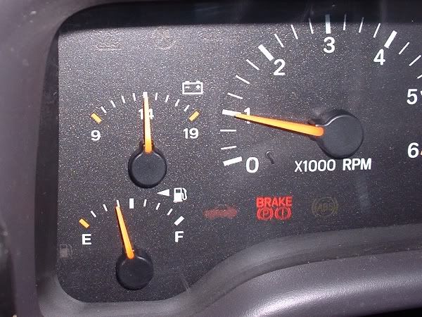
After sinking my Jeep in a muddy puddle yet again and watching the voltmeter drop for about the 4th time in 2 years I wasn’t overly concerned and continued to drive around for a little while. After 2-3 minutes I realised the alternator wasn’t going to come back on line like it always had done before, so something drastic was going to be needed. Initially I tried flooding it with clean water from a bucket while the engine was running in the hope whatever crap was causing the problem would be flushed out. This didn’t improve matters so I then got serious and emptied about a third of a can of WD40 in through any hole I could get access to. Still no improvement in the vital signs.
It was mid afternoon on the Sunday of an off-road camping weekend so I figured now would be a good time to go and knock down camp and head home. The remaining battery charge got me the 50-60 miles home but then after stopping outside the house I didn’t have enough charge to restart the motor. This was perfect timing, at least I had made it home and could throw the charger on overnight.
The next day I pulled the Alternator and for the first time since I got my Jeep I delved into the internals of the alt and just as expected found a set of gunged up brushes that were no longer making contact with the commutator/slip rings. A few moments with an old toothbrush and the alt was functional again but this inspection had revealed that the resurrection would be short lived for two reasons,
1st, the brushes only had 1-2mm of free travel left so would soon wear to the point of requiring replacement.
2nd, while the alt turned over freely, the bearings didn’t feel 100% smooth so I didn’t have faith in continued use.
Luckily I had a spare alt from a slightly older XJ and this was a very similar Nippon Denso unit which apart from the terminals at the back was physically interchangeable. I used this to act as a temporary replacement while I rebuilt the failed but more powerful unit. For info on the simple procedure to make the early alt a plug-in swap see this -
www.jeepforum.com/forum/showthread.php?t=82891800-01 type alt top and older pre-99 alt below.

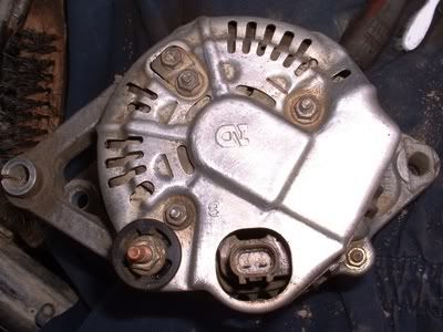

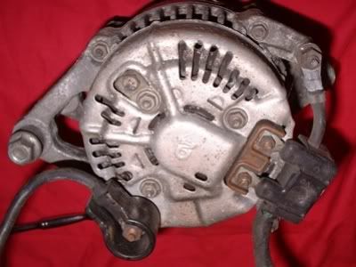
Running the temporary alt gave me the chance to strip down the failing unit and source the parts needed for the rebuild. Just for the sake of thoroughness I will start at the beginning.
Removing the AlternatorBEFORE DOING ANY WORK ON THE ALT MAKE SURE TO DISCONNECT THE BATTERY!!!
To remove the alt you will probably need to remove the electric auxiliary fan so the bottom pivot bolt can come out (when refitting the alt put the bottom bolt in from the rear so the fan doesn’t have to be removed next time the alt comes out). The fan is held by 2 x 8mm head bolts at the top and clips into the rad frame at the bottom. You will need to loosen the power steering pipes clamp from the alt bracket to allow the fan to come out and a good tug will disengage the bottom clips. The alt is then held by 15mm headed bolts on the pivot and the top clamp. Loosen these then undo the tensioner bolt about 1” to remove tension from the serpentine belt. The wire connections at the back of the alt are a plug which has a squeeze catch and the main output cable which is a 10mm headed nut under a clip on insulation cover.
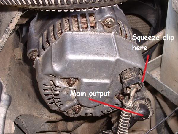
Now remove the top clamp nut and the bottom pivot bolt and the alt will easily fit out of the engine bay on the XJ models with the top mounted alt location.
Dismantling the AlternatorOnce the alt is on the bench the first thing is to remove the insulation from the main +ve output post. This is held by a 10mm headed nut which once removed allows the plastic to be lifted off.
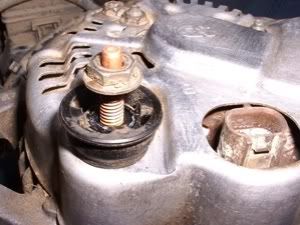
The next step is removal of the rear cover which is held by 4 x 8mm headed nuts/screws as circled.
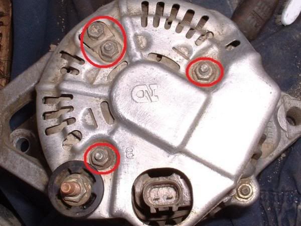
The rear cover might be ‘stuck’ by dirt and corrosion but at this stage should come off with a little persuasion. This will reveal a bright red/orange rubber cover over the brushes and then the brushes themselves can be removed by undoing the 3 x Ph#2 screws (do not be tempted to use pozi driver bits! Phillips are the best fit)

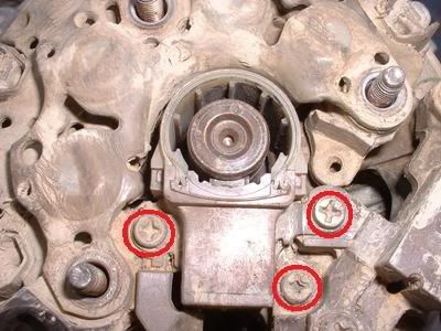
With the brushes out of the way you can now remove the component the 2 pin plug connects to which is circled in blue and secured with the 2 remaining Ph#2 screws circled in red.
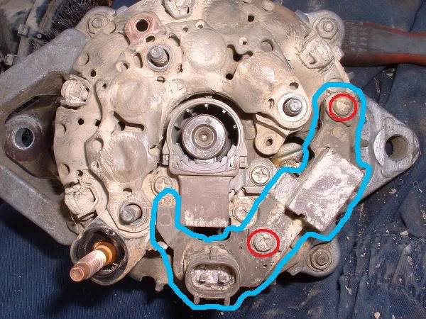
Then undo the 4 screws that secure the windings to the diode plate.
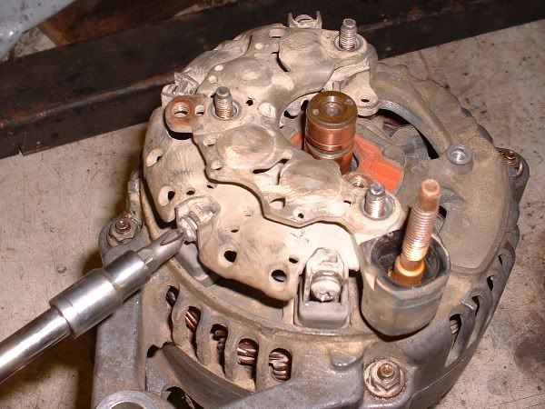
And then lift out the rubber insulators from the winding terminals.
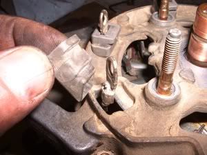
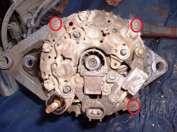
At this point I decided to split the alt casing so started by removing the 4 nuts holding the two halves together. 3 of the 4 nuts are circled in this picture with the 4th hiding by the +ve terminal post.
I had to forcibly separate the two halves even though once cleaned up they just slid firmly back together so you may be luckier than me when splitting the casing. To split the halves I used a threaded rod between the peices to open up a small gap then released the pressure and put a wedge into the opposite side which had opened up slightly before reapplying some pressure to further open the gap.

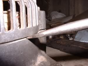
This left the slip ring end bearing stuck in the casing and this is just tapped out with a suitable drift being careful not to damage the washers that fit between the bearing and casing. Next job is to remove the front pulley so the armature can be removed from the main casing. This is a tricky job because try as I might I couldn’t secure the pulley tightly enough to undo the 22mm pulley nut without risking damage to the pulley. Fortunately the armature spindle has a 10mm hexagon on the end and by creating a special tool using a 22mm socket and some old steel I had lying around I made a tool that allowed me to fit a socket onto the 10mm hex while undoing the 22mm nut.
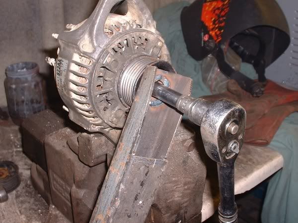

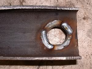
Once the pulley is off the armature slides easily out of the front bearing. The front bearing is covered by a securing plate and once this plate is removed (4 x 7mm headed bolts) the bearing can be tapped out by resting the casing on a suitable piece of pipe. Be careful not to damage the winding wires during this stage!
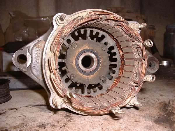

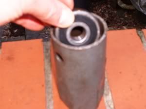
Now once you have got this far the difficult part is over. The only possible complication would be if the slip ring end bearing stayed on the armature spindle rather than in the casing. Removing it from the spindle could be tricky without some kind of puller.
Replacement partsYou should now have 2 bearings and a brush cartridge that need to be replaced. I went to an alternator specialist locally and from the TN121000-xxxx number he could supply the bearings and brushes to order at a good price. As I was a bit tight I opted to service the existing brushes and just bought the bearings from him and loose brushes with copper flex tails (cost £1 instead of £12).

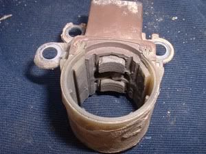
I worried about the quality of the new bearings but when they arrived they were an American made product and my regular bearing supplier couldn’t get hold of any equivalent so I suspect they might actually be OEM?
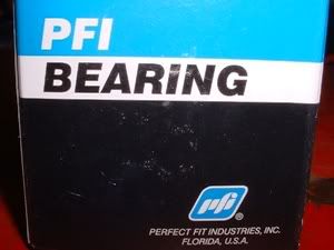
PFI part numbers for the large front bearing is 949100-3330 and the smaller one is 949100-2790
Refurbishing the brush cartridgeIf you choose to re-use the existing brush cartridge instead of replacing with a new item you only need a soldering iron to do this. First step is to remove the cover by sliding it down from the brush cartridge.

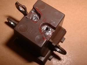
Remove the worn out brushes by melting the solder while pulling the brushes. This can be a bit tricky and takes a little more heat than you expect.
The new generic brushes are slightly different to the originals and this means the tails need to feed through the side of the spring coils before being fed into the terminal holes and soldered. Pull the tails tight enough to keep the brushes within the cartridge then trim the excess tails once the solder has cooled.

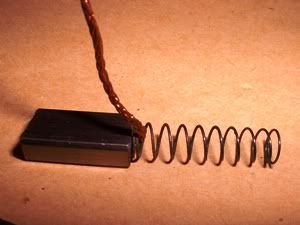

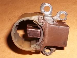
Now your brushes are ready to be re-used.
The rebuildPutting the alt back together again is really quick compared to taking it apart, sourcing parts and fixing up the brushes.
First I drifted the large front bearing in and replaced the cover plate. I found my 36mm front hub socket was the perfect size to match the outer race diameter when tapping it into the casing.
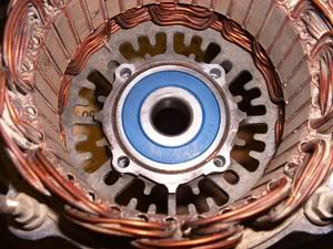
At this point I grabbed some wire wool and gave the slip rings a rub to remove the grime and give the new brushes a fresh surface to bed into. Next locate the armature into the casing and refit the pulley and 22mm nut using the special tool made earlier.
Clean out the bearing housing in the other half of the casing and then carefully drift the small bearing onto the armature with a suitable pipe or deep socket. Be very careful not to damage the slip rings and don’t forget the thin flat washer that fits between the bearing and armature here. Once the bearing is all the way home fit the flanged washer onto the spindle up tight against the bearing and rest the spring washer onto the bearing. Lower the casing onto the main body and push or tap it home till the two halves close together. Fit and tighten the four nuts to fasten the casing together.
The rubber insulators need fitting onto the 4 winding terminals now prior to installing the diode plate.

Then secure the diode plate with the four screws around the outside edge.

Replace the 2 pin plug and then the refurbed brushes
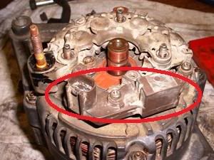
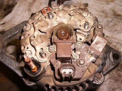
followed by the rubber cap prior to refitting the rear cover and +ve post insulation.


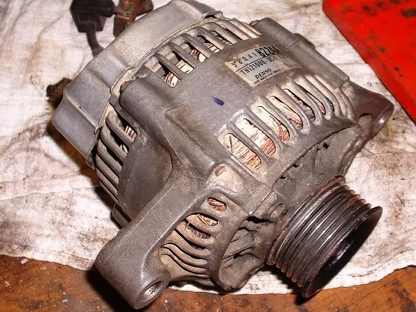
And that is the rebuild complete. You should hopefully have something that looks like this -
And see this once you reconnect the battery and start the motor -
